
In modern industrial automation, IGBT module inverters have become the backbone of high-power motor control systems. From driving massive compressors in manufacturing plants to controlling traction motors in electric vehicles, these components quietly determine whether a system runs efficiently or fails under load. Their ability to handle high voltages and currents while switching rapidly makes them indispensable across industries where precision and reliability are non-negotiable.
Yet selecting the right IGBT module is far from straightforward. Electrical engineers routinely face a maze of competing specifications, inconsistent datasheet formats, and an ever-expanding catalog of products from global manufacturers. A wrong choice can mean premature component failure, costly downtime, or compromised system performance — consequences that no project can afford.
This article cuts through that complexity by examining the latest technological trends shaping IGBT module inverters for high-power motor control. You’ll find a clear breakdown of key specifications, practical guidance on implementation, and insights into innovations from leading manufacturers including Fuji Electric. As the field evolves rapidly — driven by demands for higher efficiency, smarter diagnostics, and compact designs — staying current isn’t optional. It’s a competitive necessity for engineers who want their systems to perform at the highest level.
- The Evolution and Fundamentals of IGBT Module Inverters
- Core Components of an IGBT Module
- Key Specifications for Selecting IGBT Modules in Motor Control
- Interpreting Datasheets for Optimal Performance
- Latest Technological Trends in IGBT Module Inverters
- Smart Features and IoT Integration
- Practical Solutions: Selecting and Implementing High-Quality IGBT Modules
- Case Study: Applying Trends with Fuji Electric Modules
- The Future of High-Power Motor Control with IGBT Modules
- Recommended
- Never Miss an Important Update
- Was this article helpful?
The Evolution and Fundamentals of IGBT Module Inverters
The Insulated Gate Bipolar Transistor has come a long way since its commercial introduction in the early 1980s. First-generation IGBTs struggled with slow switching speeds and relatively high conduction losses, limiting their usefulness in demanding applications. By the 1990s, trench-gate designs and refined silicon processes dramatically reduced on-state voltage drop, opening the door to industrial motor drives. Today’s seventh-generation modules operate at voltages exceeding 6,500V with switching frequencies that would have been unthinkable two decades ago — a transformation driven by relentless pressure for energy efficiency and system compactness.
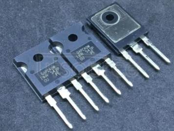
At its core, an IGBT combines the high input impedance of a MOSFET with the low saturation voltage of a bipolar transistor. In an inverter circuit, IGBTs act as high-speed switches that convert DC bus voltage into a variable-frequency AC output, allowing precise control over motor speed and torque. A typical three-phase inverter uses six IGBT switches arranged in pairs, each pair controlling one output phase. By varying the pulse-width modulation pattern across these switches, the inverter synthesizes a sinusoidal waveform that the motor interprets as a controllable AC supply.
High-power motor control applications favor IGBT modules over alternatives like MOSFETs or thyristors for several reasons. MOSFETs excel at low voltages but their on-resistance rises sharply above a few hundred volts, making them inefficient for industrial drives. Thyristors handle high currents well but lack the turn-off controllability that precise motor control demands. IGBTs occupy a practical middle ground — capable of blocking voltages from 600V to 6,500V, conducting hundreds of amperes, and switching at frequencies up to 20kHz or beyond with modern designs.
Core Components of an IGBT Module
Inside a packaged IGBT module, several elements work in concert to deliver reliable performance. The IGBT chips themselves handle voltage blocking and current conduction, while antiparallel freewheeling diodes provide a return path for inductive motor currents during switching transitions — without these diodes, voltage spikes would destroy the transistors almost immediately. A direct bonded copper (DBC) substrate bonds the semiconductor chips to a ceramic insulating layer, which in turn connects to a copper baseplate. This layered thermal interface is critical: it determines how efficiently heat generated during switching travels from the chip junction to an external heatsink. Poor substrate design creates thermal bottlenecks that accelerate aging and reduce power density. Modern modules increasingly replace traditional aluminum wire bonds with copper clips or sintered silver die-attach layers, reducing parasitic inductance and improving thermal cycling endurance — both essential qualities for motor drives that start, stop, and vary load continuously throughout their service life.
Key Specifications for Selecting IGBT Modules in Motor Control
Choosing the right IGBT module starts with understanding which specifications actually matter for your application — and why. Four parameters form the foundation of any serious evaluation: voltage rating, current capacity, switching frequency, and thermal resistance. Getting any one of these wrong can result in either an overengineered, expensive design or a system that fails under real operating conditions.
Voltage rating defines the maximum collector-emitter voltage the module can block safely. For motor control, engineers typically apply a derating factor of 50–60%, meaning a 600V bus would require a module rated at 1,200V minimum. This buffer absorbs voltage spikes from inductive switching transients that would otherwise punch through the device. Current capacity — expressed as both continuous DC current and peak surge current — must account for motor startup conditions, where inrush currents can reach six to eight times nominal values. A module that handles steady-state load comfortably may still fail during repeated acceleration cycles if its surge rating is underspecified.
Switching frequency directly influences motor control quality. Higher frequencies produce smoother current waveforms with less harmonic distortion, reducing motor heating and acoustic noise. However, every switching event generates losses proportional to frequency, so there’s a practical ceiling determined by the module’s thermal budget. Most industrial drives settle between 4kHz and 16kHz, balancing waveform quality against efficiency. Thermal resistance — measured as junction-to-case (Rth(j-c)) — quantifies how effectively the module conducts heat away from its chips. Lower values allow higher power dissipation without exceeding the maximum junction temperature, which is typically 150–175°C for modern silicon IGBTs.
A practical selection checklist should cover these criteria: confirm voltage rating at 2× the DC bus voltage, verify continuous and peak current ratings against worst-case load profiles, match switching frequency to your PWM strategy, and calculate total power dissipation using the module’s datasheet loss curves to ensure Rth(j-c) keeps junction temperature within safe limits under maximum ambient conditions.
Interpreting Datasheets for Optimal Performance
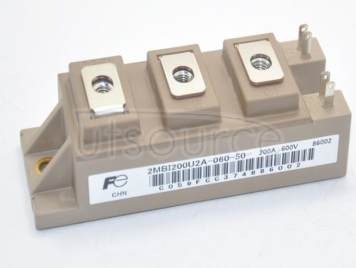
Datasheets from manufacturers like Fuji Electric pack considerable information into dense tables and graphs — knowing where to focus saves time and prevents misinterpretation. Start with the absolute maximum ratings table, but don’t design to those limits. The application curves — particularly switching energy (Eon, Eoff) versus collector current, and output characteristics showing VCE(sat) versus IC — reveal how the device actually behaves under your specific operating conditions. Fuji Electric’s datasheets, for example, provide these curves at multiple junction temperatures, which matters because VCE(sat) increases with temperature in IGBTs, directly raising conduction losses during sustained operation. Cross-referencing the thermal impedance transient curves (Zth(j-c)) lets you model junction temperature under pulsed loads rather than relying solely on steady-state values. When comparing modules across manufacturers, normalize efficiency comparisons to identical test conditions — bus voltage, gate resistance, and junction temperature — since small differences in test setup can make a mediocre device appear competitive on paper. Platforms like UTSOURCE can be useful at this stage, as they aggregate component listings from multiple manufacturers and provide access to datasheets in one place, helping engineers cross-reference specifications more efficiently during the evaluation process.
Latest Technological Trends in IGBT Module Inverters
The IGBT module landscape is shifting faster than at any point in the past decade, driven by three converging pressures: tighter energy efficiency regulations, the explosive growth of electric vehicle powertrains, and industrial demand for more compact drive systems. Power density — the amount of power a module can handle per unit of volume or weight — has become the defining competitive metric. Manufacturers are achieving density gains through thinner silicon wafers, optimized chip layouts, and advanced packaging that eliminates unnecessary parasitic elements. Fuji Electric’s seventh-generation X-Series modules, for instance, demonstrate measurable reductions in switching losses compared to previous generations, enabling higher output power within the same footprint. This matters enormously in applications like servo drives and traction inverters where cabinet space is at a premium.
Thermal management has seen equally significant innovation. Traditional thermal interface materials are giving way to sintered silver bonding, which offers substantially lower thermal resistance and superior fatigue resistance under repeated thermal cycling. Double-sided cooling architectures — where heat dissipates from both the top and bottom of the module — are moving from concept to commercial reality, effectively halving the thermal path length. Some manufacturers now integrate microfluidic cooling channels directly into the baseplate, allowing liquid coolant to flow millimeters from the chip junction. These advances collectively push maximum junction temperatures higher while extending operational lifetime, a critical consideration for industrial drives expected to run continuously for a decade or more.
On the materials front, silicon carbide (SiC) is increasingly influencing IGBT module design philosophy, even in applications that retain silicon chips. Hybrid modules pairing silicon IGBTs with SiC freewheeling diodes have become commercially mainstream, capturing most of the efficiency benefit of full SiC at a fraction of the cost. Fuji Electric has pursued this hybrid approach across several product families, delivering lower reverse recovery losses in the diode stage while keeping the proven reliability profile of silicon IGBT chips for the switching elements.
Smart Features and IoT Integration
Beyond raw electrical performance, the most consequential trend reshaping IGBT module design is intelligence. Modern modules increasingly incorporate onboard sensors and gate driver ICs that monitor junction temperature, collector current, and supply voltage in real time. Rather than relying on external protection circuits to detect fault conditions after they occur, these integrated systems respond within microseconds — desaturating the gate drive or triggering a soft shutdown before overcurrent or overtemperature conditions cause irreversible damage. Fuji Electric’s intelligent power modules exemplify this direction, embedding protection logic directly into the module housing to reduce external component count and improve response latency.
The deeper value of onboard sensing emerges when modules connect to broader IoT ecosystems. By streaming thermal and electrical health data to a plant-level monitoring platform, engineers can track degradation signatures — gradual increases in on-state voltage or rising thermal resistance — that precede failure by weeks or months. This predictive maintenance capability transforms IGBT modules from passive components into active contributors to system uptime. For high-power motor control installations where unplanned downtime carries significant production costs, the economic case for smart modules is straightforward: the data they generate pays for itself many times over in avoided failures and optimized maintenance scheduling.
Practical Solutions: Selecting and Implementing High-Quality IGBT Modules
Translating specification knowledge into a reliable procurement and implementation process requires a structured approach. Start with supplier evaluation before committing to any module. Established manufacturers like Fuji Electric publish comprehensive application notes alongside datasheets, maintain consistent lot-to-lot quality through controlled fabrication processes, and offer direct engineering support — advantages that generic suppliers rarely match. For sourcing and comparing components across brands, electronics distributors such as UTSOURCE offer broad catalogs of automation accessories and industrial semiconductors, which can be practical when evaluating multiple module options or sourcing replacements for legacy systems. Request qualification test reports covering thermal cycling endurance, humidity resistance, and short-circuit withstand capability. A module that passes IEC 60747-9 testing under realistic conditions gives far stronger reliability assurance than one validated only under ideal bench conditions.
Once you’ve shortlisted candidates, simulate the thermal stack before ordering samples. Use the module’s Rth(j-c) value combined with your heatsink’s thermal resistance and expected power dissipation to calculate worst-case junction temperature. If the result approaches 150°C under maximum ambient and load conditions, either select a module with lower thermal resistance or improve the cooling solution. Apply thermal interface material consistently — uneven application creates air pockets that raise effective thermal resistance by 20–30% in practice, negating the advantages of a well-specified module.
During circuit integration, gate drive design deserves as much attention as the module itself. Use the manufacturer’s recommended gate resistance values as a starting point; increasing Rg slows switching and reduces EMI but raises switching losses, while decreasing it does the opposite. Keep gate drive PCB traces short and tightly coupled to minimize parasitic inductance that causes voltage ringing at turn-off. For high-power three-phase inverters, use isolated gate drivers with active Miller clamp circuits to prevent spurious turn-on in the complementary switch during fast switching transitions.
Testing before full commissioning should follow a defined sequence: verify gate drive signals at low voltage with no load, then gradually increase DC bus voltage while monitoring switching waveforms for excessive overshoot. Run thermal imaging during load tests to confirm heat distribution matches simulation predictions. Document baseline on-state voltage readings at commissioning — these become reference values for future predictive maintenance comparisons.
Case Study: Applying Trends with Fuji Electric Modules
Consider a 200kW industrial pump drive retrofit where the engineering team replaced aging sixth-generation modules with Fuji Electric’s seventh-generation X-Series IGBT modules incorporating SiC freewheeling diodes. The hybrid configuration reduced diode reverse recovery losses by approximately 60%, allowing the switching frequency to increase from 4kHz to 8kHz without exceeding the thermal budget. The smoother output waveform cut motor winding temperature rise by several degrees, directly extending insulation service life. Onboard temperature sensing fed real-time junction data to the plant’s monitoring system, replacing scheduled preventive maintenance intervals with condition-based service visits. Within the first operating year, the team identified one module showing gradual thermal resistance increase — a precursor to solder fatigue — and replaced it during a planned shutdown rather than facing an unplanned failure. The key takeaway for engineers: combining advanced module selection with smart monitoring infrastructure doesn’t just improve efficiency; it fundamentally changes how maintenance resources are allocated, shifting from reactive firefighting to proactive system management.
The Future of High-Power Motor Control with IGBT Modules
IGBT module inverters continue to evolve at a remarkable pace, reshaping what’s possible in high-power motor control. From the shift toward hybrid SiC configurations and sintered silver bonding to the integration of onboard diagnostics and IoT-connected health monitoring, the technology available to engineers today is fundamentally more capable than what existed even five years ago. These aren’t incremental refinements — they represent a genuine leap in power density, thermal endurance, and system intelligence that changes how drives are designed, operated, and maintained.
Understanding specifications remains the non-negotiable foundation of good module selection. Voltage derating, thermal resistance calculations, and switching loss analysis separate reliable designs from ones that fail under real operating stress. Equally important is choosing suppliers who back their products with rigorous qualification data and application engineering support — qualities that become critical when a motor drive is expected to run continuously for a decade in a demanding industrial environment.
The practical solutions outlined here — from structured supplier evaluation and thermal simulation to gate drive optimization and commissioning-phase baseline documentation — give engineers a repeatable framework for implementation rather than a one-time checklist. Applied consistently, they reduce both development risk and long-term operating costs.
Looking ahead, the convergence of wide-bandgap materials, advanced packaging, and digital intelligence will continue pushing IGBT module performance higher. Engineers who stay current with these developments and apply them systematically will build motor control systems that are not only more efficient today, but better positioned to meet the efficiency and reliability demands of tomorrow’s industrial landscape.
Never Miss an Important Update
Get the latest tech news, how to guides, AI updates, telecom offers, and useful tools delivered instantly. Join our WhatsApp Channel or add WikiTechLibrary as your preferred source on Google.


